Choosing Roll Forming Machine Components is not a parts-list exercise. Each roll stand, shaft, bearing, gearbox, guide, and cutoff unit affects profile accuracy, uptime, and maintenance. The right combination depends on the material, its thickness and strength, the profile geometry, production speed, and required tolerances. Small details matter. A poorly supported shaft, for example, can contribute to deflection and inconsistent forming.
Industry scale helps explain why component choices deserve careful review. World Steel Association’s World Steel in Figures 2024 reports global crude steel production of about 1,892 million tonnes in 2023. This figure does not measure roll forming demand directly. It does, however, show the vast material base served by steel-processing equipment. Production volume alone is not a buying guide. A machine designed for thin-gauge panels may not suit heavier sections, even when both process steel.
A practical comparison should examine roll material and hardness, bearing load ratings, shaft diameter, frame stiffness, drive configuration, and spare-parts availability. Ask suppliers how they verify tolerances and what maintenance intervals they recommend. Request evidence, not only promises. A polished specification sheet can still leave important questions unanswered. That is easy to miss. This guide outlines the key checks, trade-offs, and questions buyers can use when assessing components for a particular production line. Some choices will remain compromises; the goal is to make them visible before installation.
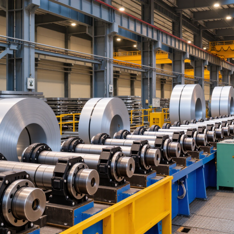
Start with the finished profile, not the machine catalog. Specify cross-section, critical dimensions, bend angles, cut length, and allowable twist. A dimensioned drawing helps, but a physical sample can reveal details the drawing misses. Record the material grade, thickness range, coating, and mechanical properties, especially yield strength. World Steel Association’s World Steel in Figures 2024 reports about 1.89 billion tonnes of crude steel production in 2023. That scale does not make all steel interchangeable: grade, thickness, and coating affect forming forces, springback, and roll wear. Do not guess.
Match the requirements to the components. A narrow thickness range may allow simpler roll adjustments; frequent material changes call for flexible setup and clear changeover procedures. Thin strip can buckle if stands, guides, or entry alignment are poorly matched. Confirm the required line speed, shift pattern, annual volume, and cut-off accuracy before sizing the drive and cutting system. Include realistic downtime and scrap allowances. A sample helps. But it is not the whole story. Test the proposed setup with the actual material when possible, then review dimensional results across a production run. A first-off part can look perfect while later pieces drift. That possibility is easy to overlook.
| Requirement | Example Data or Design Input | Component Selection Implication |
|---|---|---|
| Finished product profile | Specify the cross-section, dimensions, bend angles, lip or flange details, and required cut length. | The profile determines roll geometry, forming sequence, station layout, guides, and cutoff tooling. |
| Material grade and strength | Identify the material standard and expected yield strength; for preliminary planning, mild steels may be around 150–350 MPa, while some high-strength grades exceed 550 MPa. | Higher-strength material generally requires more forming force and may call for stronger shafts, frames, drives, and roll materials. |
| Material thickness | Define the minimum, nominal, and maximum thickness. Many applications fall within approximately 0.3–3.0 mm, but machine capacity is application-specific. | Thickness affects roll gaps, pass design, shaft loading, forming force, and cutoff capacity. Confirm the full thickness range with the machine designer. |
| Strip width and coil dimensions | Provide strip width, coil outside diameter, inside diameter, and maximum coil mass. These values vary considerably by product and facility. | These inputs size the entry guides, uncoiler, mandrel, coil car, and loading equipment. |
| Profile complexity | Count bends and assess tight radii, hems, offsets, narrow flanges, and asymmetric features. | More complex shapes may need additional forming stations, carefully sequenced passes, and dedicated side or edge guides. |
| Dimensional tolerances | Set allowable limits for profile dimensions, straightness, twist, and cut length according to the product specification. | Tighter tolerances may require more stable stands, precise roll adjustment, reliable material guidance, and calibrated length measurement. |
| Target production rate | State the required output in pieces per hour or metres per minute, including typical and peak demand. | Production rate influences drive sizing, line speed, feeder capacity, cutoff cycle, and whether a flying cutoff is appropriate. |
| Drive and transmission | Specify the required speed range, expected load, duty cycle, and whether independent or grouped station drives are preferred. | Motor, gearbox, and transmission capacity should match the material, thickness, profile, and planned operating speed. |
| Roll tooling and shafts | Choose roll material and shaft dimensions based on material hardness, forming load, product width, and expected tool life. | Adequate shaft stiffness and appropriately hardened, finished rolls help control deflection, wear, and surface marking. |
| Cutoff method | Select a stationary cutoff for suitable lower-speed operations or a synchronized flying cutoff when continuous production is required. | The cutoff must match material thickness, profile shape, line speed, cut-length accuracy, and acceptable end condition. |
| Controls and changeover | Define recipe storage, length control, speed adjustment, fault indication, and the frequency of product changeovers. | Frequent changeovers can justify quick-adjust features, documented setup values, and accessible operator controls. |
| Safety and maintenance | Assess guarding, emergency stops, safe coil handling, access for inspection, lubrication, and tool replacement. | Include suitable guarding and safety controls, and allow practical access to components that need routine maintenance. |
Note: The ranges shown are preliminary planning examples, not universal machine limits. Confirm the final design against the exact profile drawing, material specification, tolerances, and production target.
Check working width, roll-station spacing, and material thickness. Ask for alignment and load-test records. A heavy frame may still twist.
Match motor capacity, gearbox ratio, and speed control to your material and production schedule. Look for steady torque at your actual line speed.
Inspect guide adjustment, pinch-roll grip, and coil-loop control. Watch the strip closely. Small flaws show up fast.
Run a short trial using your real coil. Look for strip drift, slipping, vibration, and heat around the gearbox.
Compare shaft diameter, keyway size, bearing load, and operating speed with the machine specifications. Measure installed parts, not only drawings. Drawings can be outdated.
Match roll material and profile to the product being formed. Check station spacing, too. A small mismatch can cause edge marks or uneven bends.
Ask how often bearings, seals, and cutting tools need inspection. Check whether grease points are accessible and routine replacements require special tools.
Request part numbers, tolerances, and safe adjustment steps. Keep records of noise, heat, and wear. These clues may reveal trouble early.
Ask who responds to technical questions and what measurements they need. Request written specifications and realistic lead times. Promises alone are hard to judge.
Choosing Roll Forming Machine Components starts with a clear understanding of the product, material, target profile, and expected production volume. These requirements guide the selection of roll tooling and forming sequence, as well as the machine frame, drive system, and feeding components. Each part should be suited to the material’s thickness and strength and capable of supporting consistent, efficient operation.
Cutting equipment, controls, and safety systems should match the production process and finished product requirements. Before making a decision, verify that all components work together and can be maintained without unnecessary downtime. Consider access to replacement parts, technical guidance, and ongoing supplier support as part of the evaluation. A well-matched component package can improve forming consistency, simplify operation, and help the machine meet production needs over time.

 Xiongchang